Last week I ordered a Teensy 3.5 and an 8 digit display similar to Ulrich's', keeping in mind that it had to use two 74HC595 shift registers.
If the part "74HC595 shift registers" doesn't make any sense to most of you, relax. It wasn't too long ago that it didn't make sense to me either.
Lets break it down
One "number" has 7 segments. Pretend that each "bar" in that segment requires a positive voltage. So naturally you'd also need a negative line going in, right? Kinda. Each number segment also has a "dot" or period in the bottom right corner. That makes 8 leads. But then you have two more leads, I'll call them "ground" wires in this case.
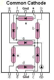
Two leads are ground, and can go to a common ground on the Arduino. So lets call it 9 wires just for one number segment.
But this is an 8 digit display! That's going to be a lot of wires running around.
Enter the "shift register"
To over simplify - it uses only three lines from the Arduinos to address all the separate LEDs that make up a 7 segment
(plus the dot) display through those two 74HC595 chips FOR ALL 8 DIGITS!
To complicate matters there are two, more or less, incompatible systems -
common anode and common cathode. It is possible to work around the differences, but it's MUCH better just to get the right one.
And on a beginners level that's all you need to know for now -get the right part and follow the directions.
So I knew that Ulrich's display used the 74HC595 shift registers, and I bought a similar display board - the
XINY 8-Digit Digital Display Control Module 8-Digit 7 Segment Digital LED Display Tube $7.60. If I made a mistake, I can live with it.
So I now have a Teensy 3.5 and an 8 digit display similar to Ulrich's'. BTW - I could have gotten the display cheaper, but it would have taken much longer. A few dollars won't make a difference.
NEXT - time to play.
I found some decent software to test the display here -
playground2014. See the attached text file. Just copy and paste into the Arduino IDE.
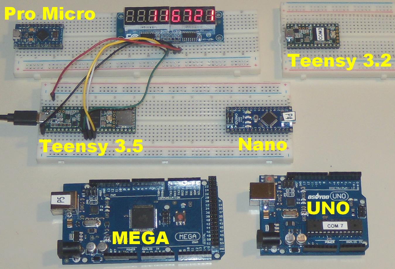
It worked so well that I went a little crazy and tested it on all the Arduinos that I have. Only one didn't work right, and that's probably my fault.
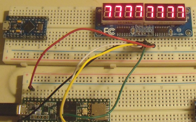
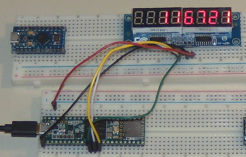
Any way. The unmodified code worked on all of these
Sorry for the poor picture quality. In real life all the numbers are evenly lit, and quite bright.
The program starts on the right end. It goes through each number, 0 through 9, and then blacks out. It now does another run, 0 through 9, on the next 7 segment digit.
In this picture, it's testing the fourth digit.
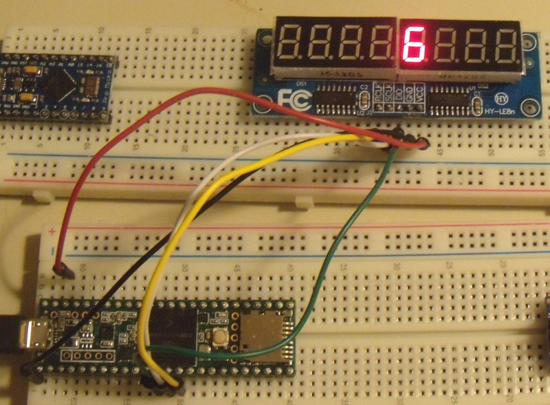 Once it has checked each number segment, it tests ALL number segments at the same time, 0 through 9.
 The grand finally is that it does a n+1 count until all digits are filled.
That's all folks.